Liner construction used in major munich project - not to be outdone in terms of performance.
Sensible alternative
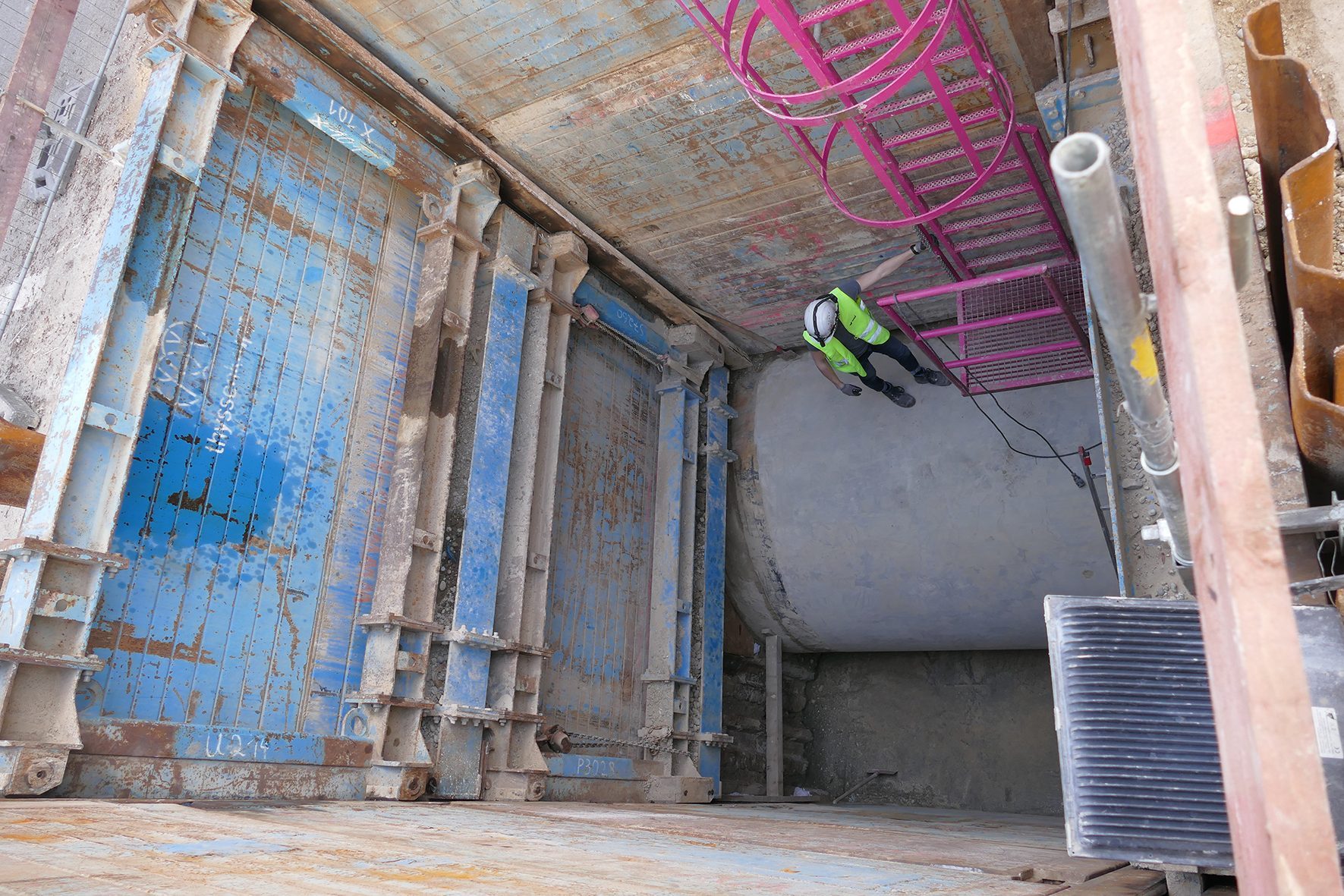
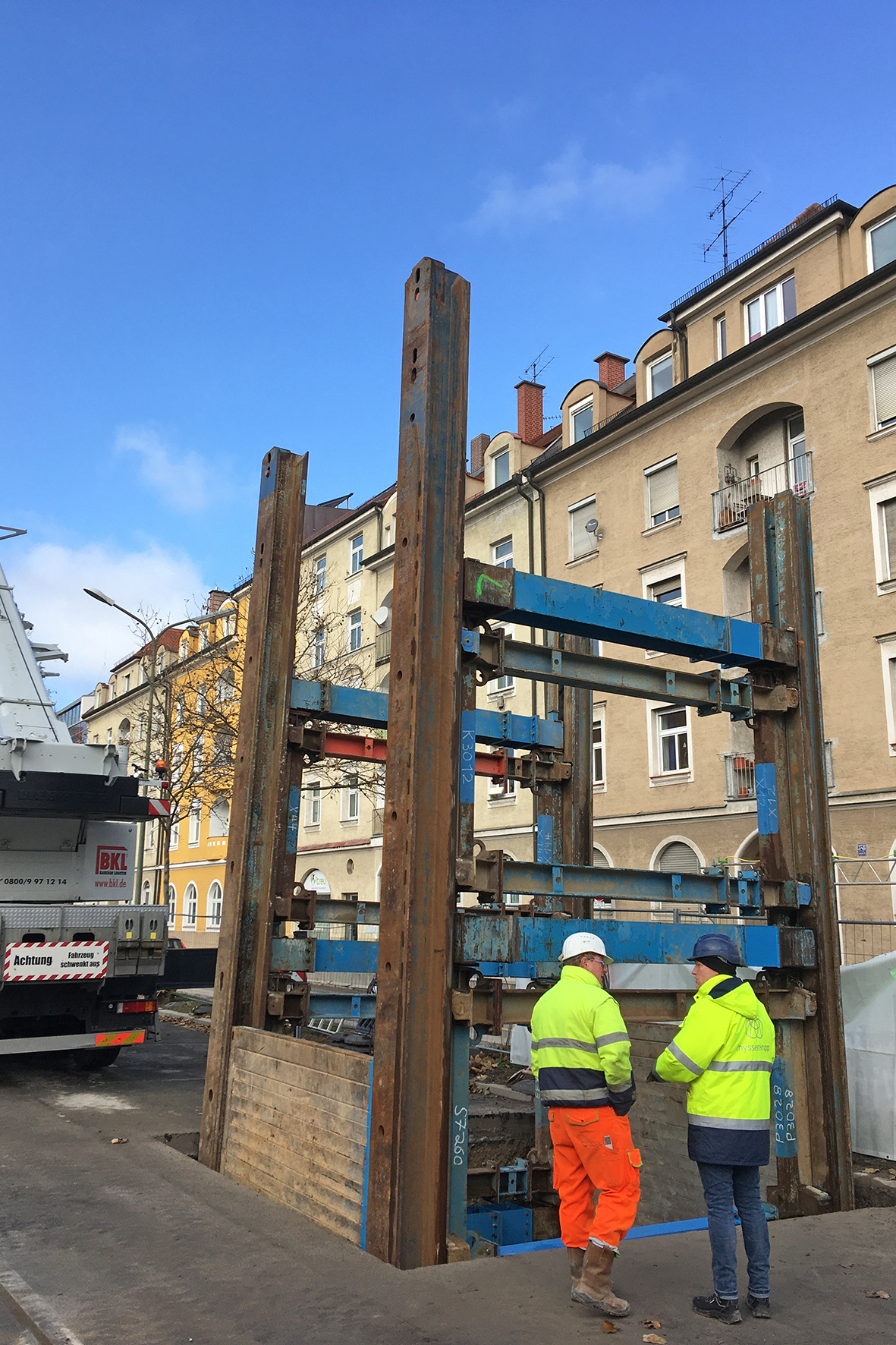
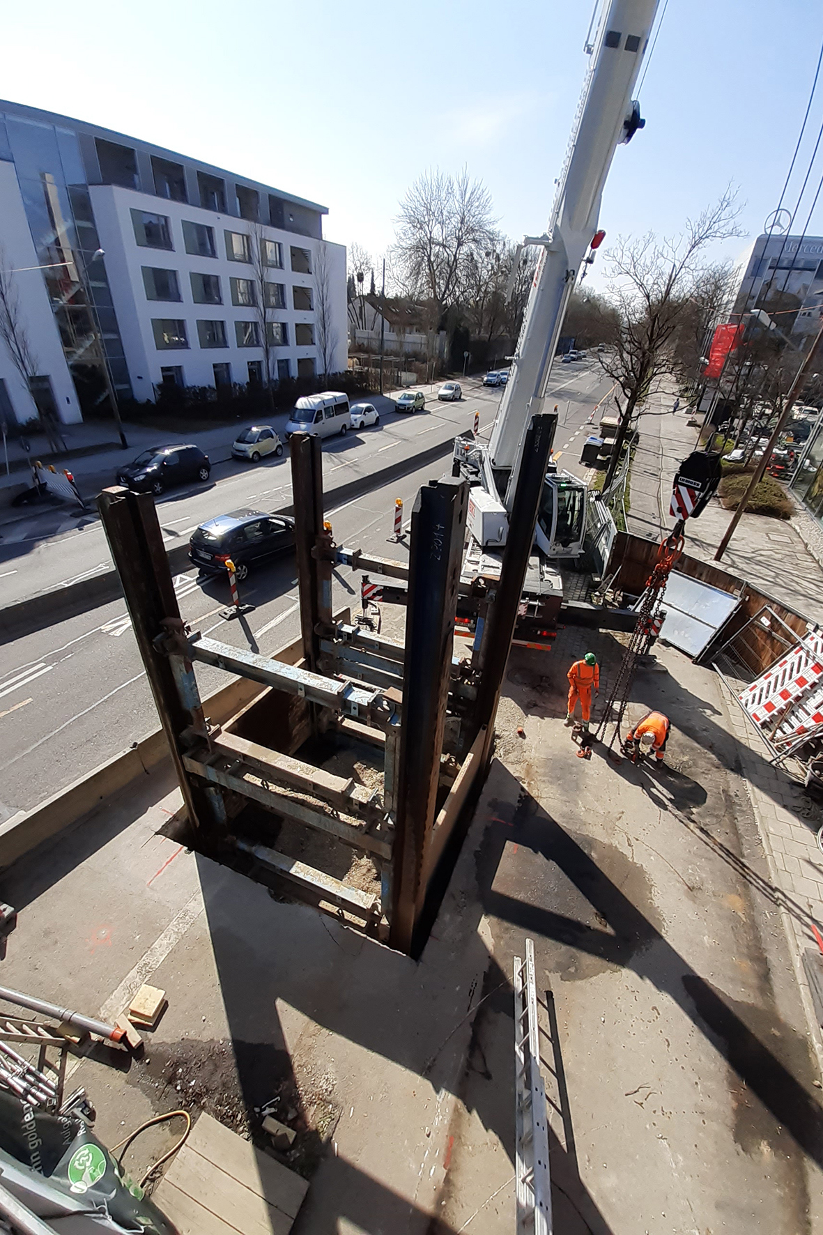
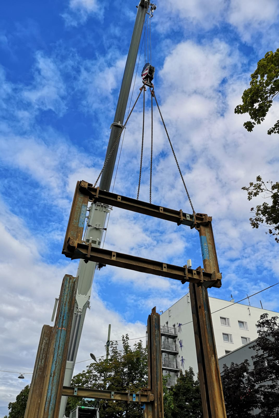
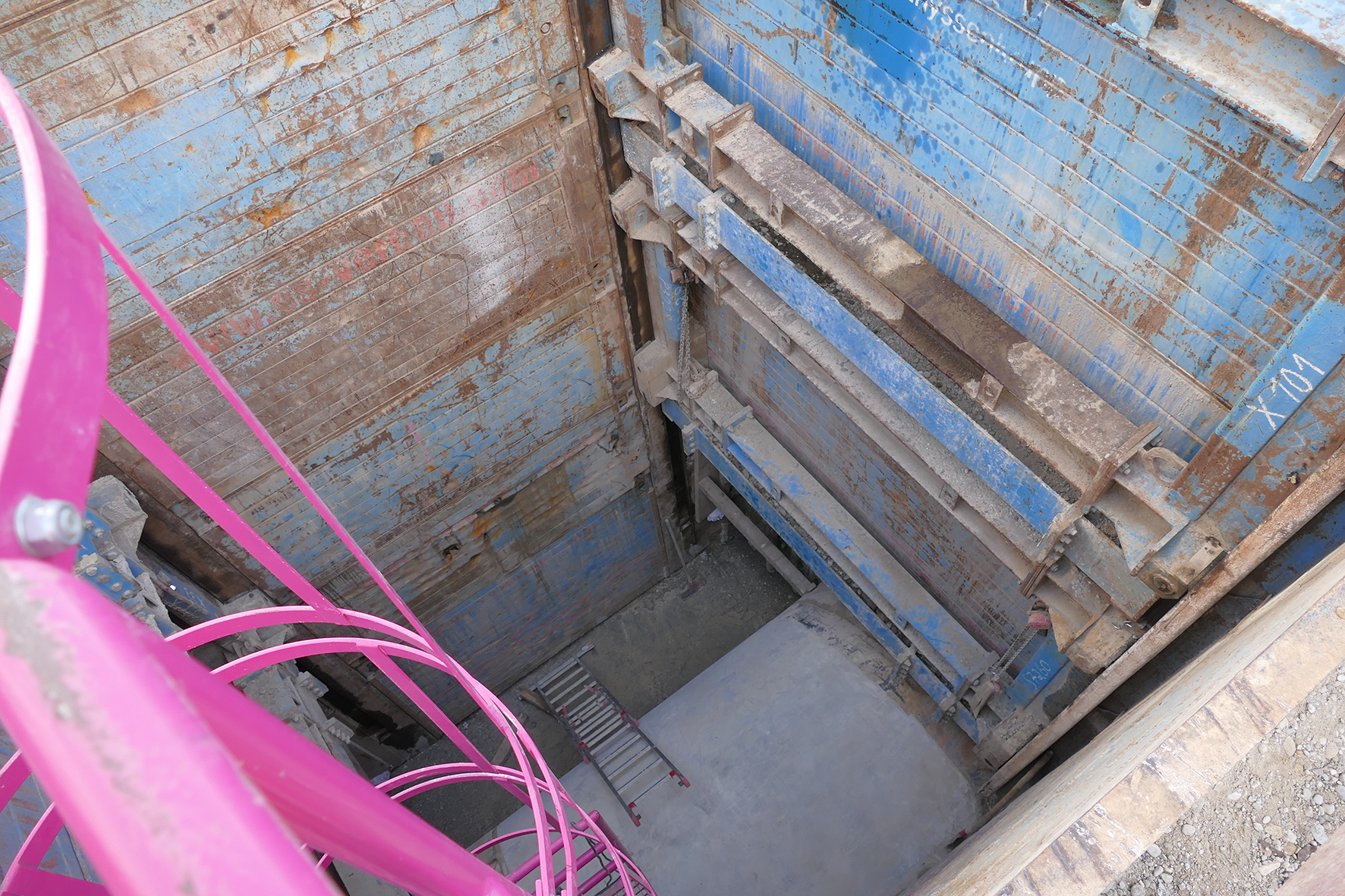
In contrast to pile driving or vibration - for example, when sheet piles are used - the construction environment is subjected to much less vibration when linear shoring is installed. In vertically installed double slide rails, inner and outer shoring panels are held in such a way that they slide past each other and can be brought to the required depth. Two flexurally rigid carriages, adjustable in height according to the advancing construction depth, keep the girders and shoring panels at the same distance apart at all times; the trench width remains the same in every construction phase.
Stepped in the truest sense of the word
In the longitudinal direction of the new sewer, the elements of the shoring system could be installed on the side facing away from the pipe using 9.13-meter-long girders up to the bottom of the excavation. On the other side, the 7.13 meter long girders and the shoring panel ended directly on the jacking pipe - as did the shoring on the head ends, which could also only be installed as far as the pipe crown of the jacking pipes. In order to secure the remaining working space, the approx. 2.70 meter high area next to the pipe string up to the bottom, the construction partners decided to install sheet piles behind the shoring on the head side up to the pipe and next to it up to the bottom. In order to secure this structure in accordance with the structural requirements, two head shoring adapters were integrated into the linear shoring system in addition to the two roller units. Like the roller units, the head shoring adapters are guided in the profile of the linear shoring soldiers, can be adjusted in height at any time and are flush with the head edge of the shoring system. A temporary support between the pipe and the lateral shoring wall secured the sheet piles during this construction phase. It could be removed again after concreting a 25-centimeter-thick clean layer.
you might also be interested in
-

Saxony-Anhalt is also battening down its hatches
Since the “flood of the century” in 2002, Saxony-Anhalt has completed a whole range of flood defence measures, especially for upgrading dykes. One weak spot was the Elbtor alongside the River Elbe in Schönebeck.
To the post -
Feeder Line
Old manholes were uncovered and demolished, and in the course of laying the new pipeline, the original structures were replaced by new manholes made of precast reinforced concrete.
To the post -
Flood Protection in Fargo, North Dakota, USA
The city of Fargo is located on the Red River, which repeatedly flooded existing flood defences and roads during the winter months.
To the post